Capacitor Panel Control Wiring Diagram
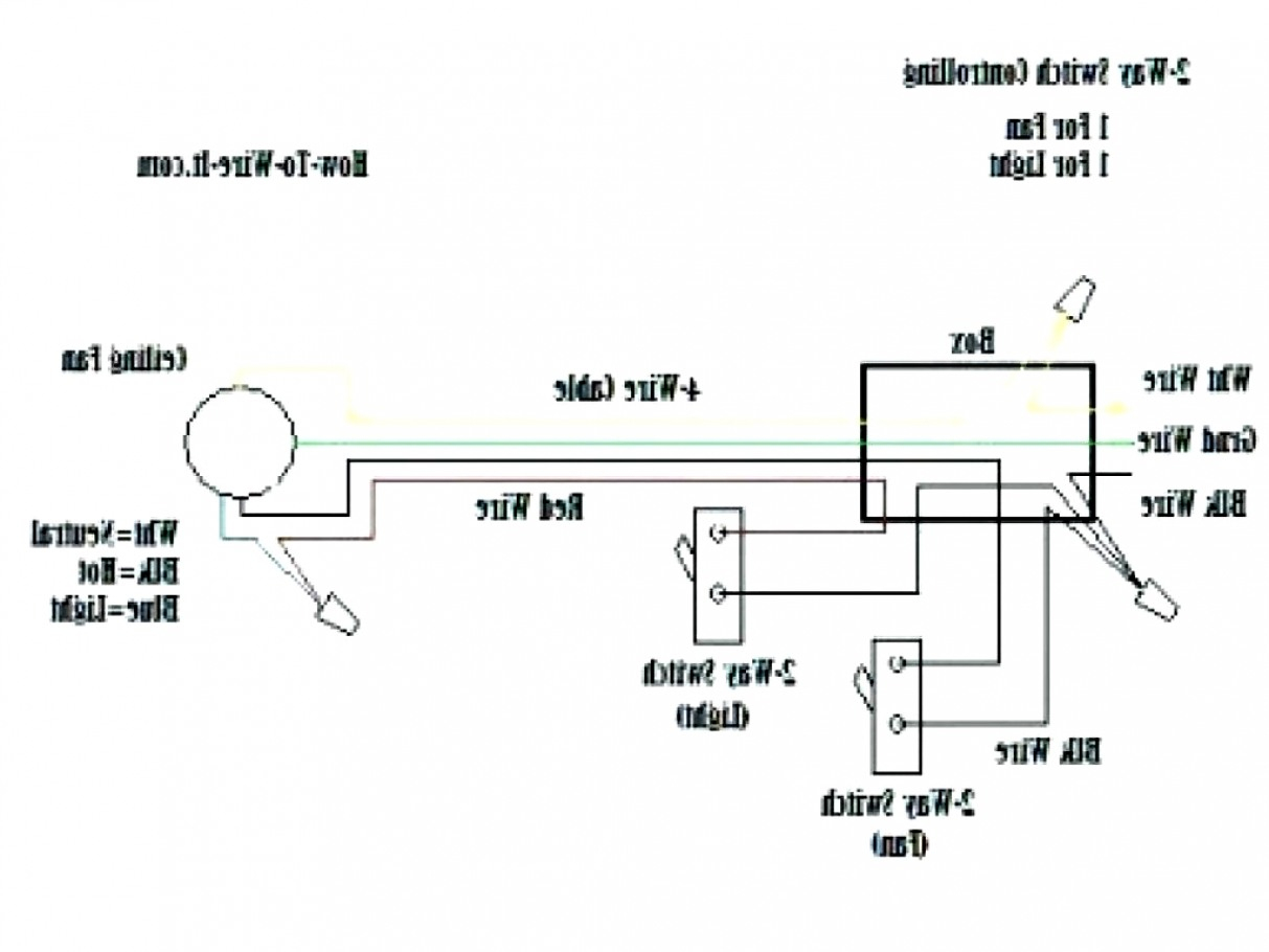
This diagram illustrates wiring for one switch to control 2 or more lights. To reset the breaker locate the short by removing all wires connected to the.
Capacitor Bank Control Wiring Diagram

The constructor electrical drawing software and circuit simulator software is a great training tool for teaching troubleshooting!

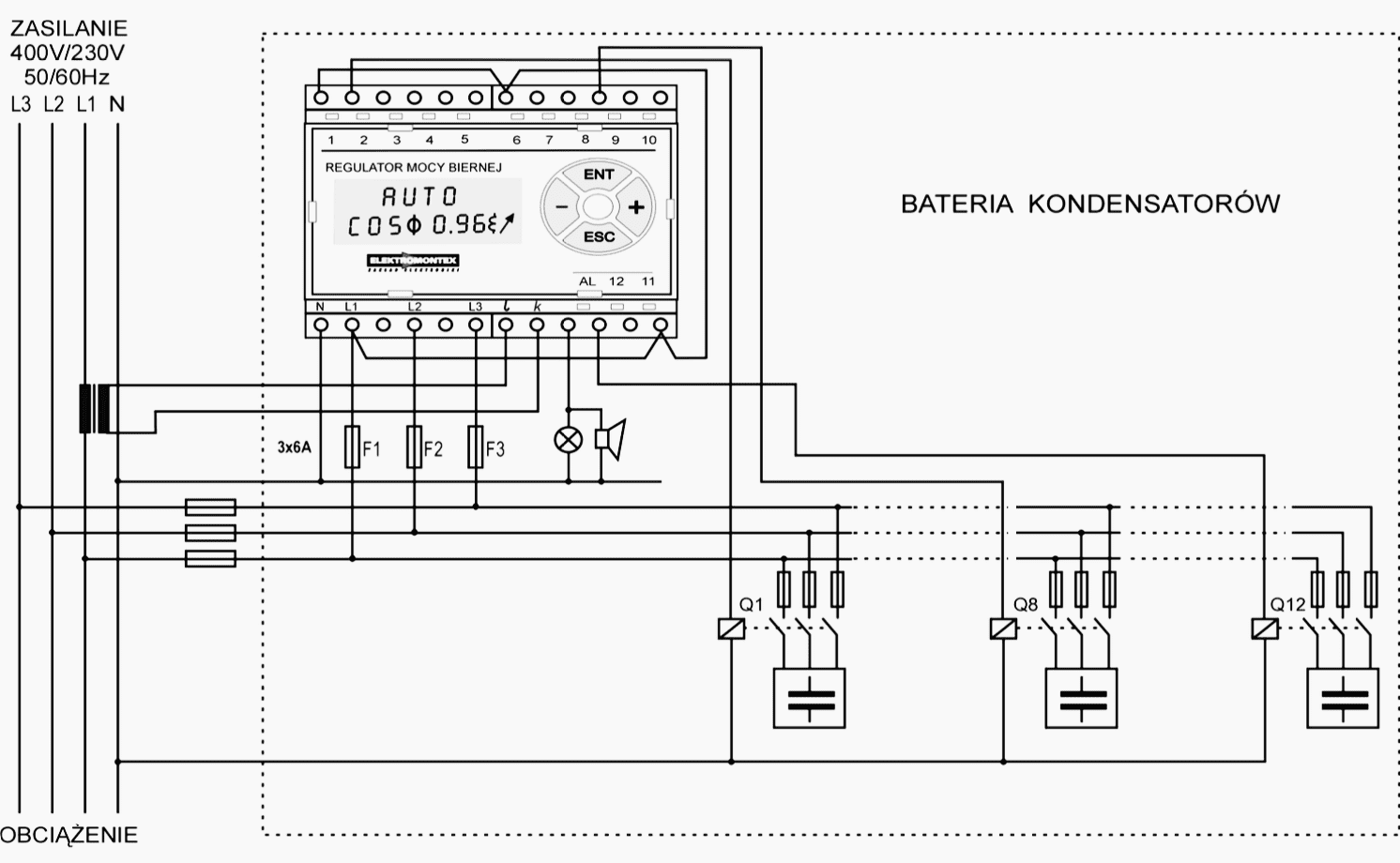
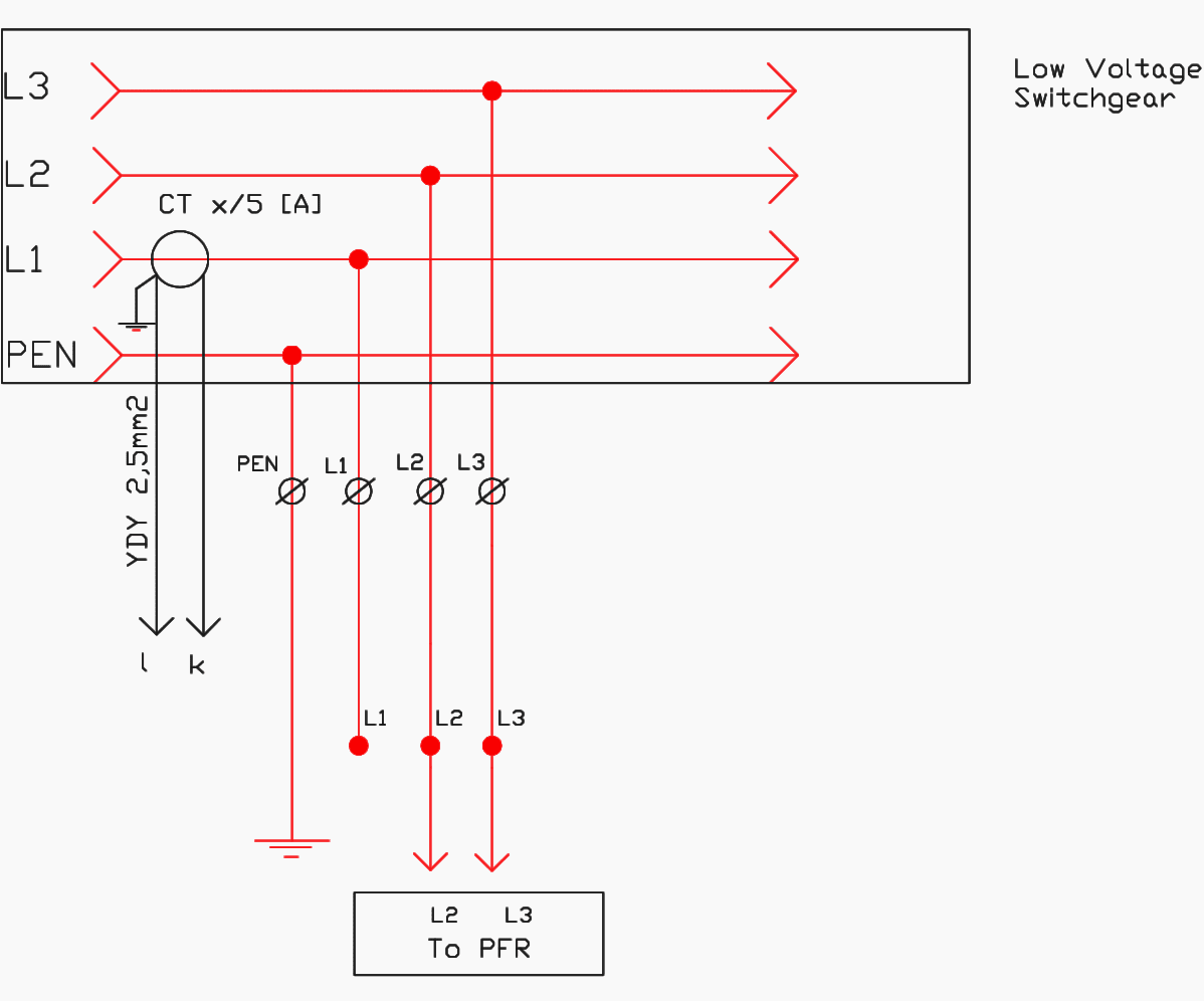
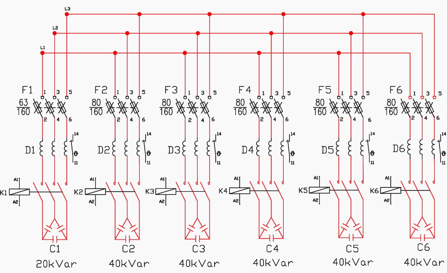
Capacitor panel control wiring diagram. The aim of project called reactive power compensation panel was to design capacitor bank with rated power of 200kvar and rated voltage of 400v adapted for operation with mains where higher order harmonics are present. 4oz bottle round metal 17oz bottle round plastic. Single phase motor wiring diagram with capacitor start.
By vallery masson updated on november 3, 2021 november 3, 2021 leave a comment on capacitor panel control wiring diagram. And local codes 208/230 vac, 60 hz, 3 ph. November 3, 2021 on capacitor panel control wiring diagram.
Electrical wiring diagrams of a plc panel. Panel must be ordered with the proper amp rating matching that of the pump. A wiring diagram is an easy visual representation in the physical connections and physical layout of an electrical system or circuit.
The simplest approach to read a home wiring diagram is to begin at the source, or the major power supply. In monostable operation, the control pin5 is connected to ground through a 0.01 uf capacitor. Control panel for 1 h p submersible pumps with timer ltems t 1050 ewatercart com.
Ahu control panel wiring diagram pdf. 1v rms for 1v rms output maximum output voltage: Improper connection may result in damage to the motor and capacitors.
The simplest solution is to wire a 3k3 1/4w resistor in series to the output capacitor of the last module (i.e. Control voltage pin 5 pin5 can be used to control the working of ic by providing a dc voltage at pin5. Baldor 7 5hp motor capacitor wiring diagram ~ welcome to our site, this is images about baldor 7 5hp motor capacitor wiring diagram posted by benson fannie in diagram category on nov 30, you can also find other images like wiring diagram, parts diagram, replacement parts, electrical diagram, repair manuals, engine diagram, engine scheme.
This permits the control of the timing cycle manually or electronically. Ac switch wiring diagram.a wiring diagram is a streamlined standard photographic representation of an electric circuit. How to wire an air conditioner for control 5 wires the diagram below includes the typical control wiring for a conventional central air conditioning systemfurthermore it includes a thermostat a condenser and an air handler with a heat source.
Rectification of a three phase supply using diodes. Single phase transformers for three phase operation. Wiring diagram hunter ceiling fan kenworth t800 fuse panel gravely ra rewel2 jeanjaures37 fr.
Sheet metal 230 v ac ahu starter control panel. If not the arrangement will not. 250mv rms for 1v rms output tone control module input sensitivity:
Electrical circuit diagram design software with circuit simulator. Single phase motor wiring diagram with capacitor sources. Motor wiring diagram explained new symbols archaic ely patent.
They allow a small circuit to rule a future flow circuit using an electromagnet to manage the flow of electricity inside the circuit. Apfc panel 3 phase capacitor bank wiring diagram schematic. Collection of hvac control panel wiring diagram.
When the tank is low on water, the float switch activates the pump motor and turns a red pilot light on. With single phase motor with capacitor forward and reverse wiring Three phase harmonic filters connected to 440 v bus.
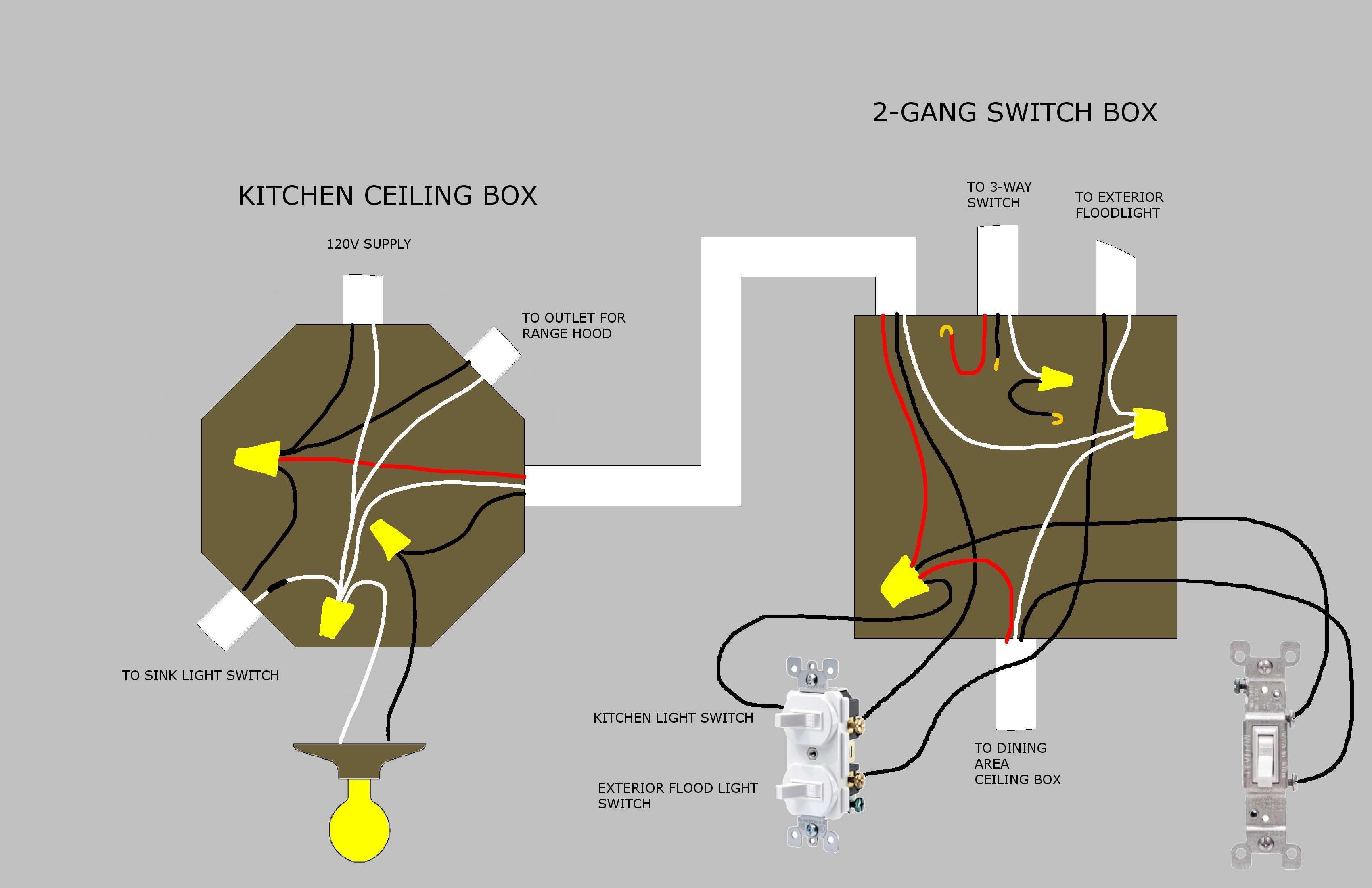
I am adding an outside light to my 1941 house. 2010 jeep grand cherokee wiring diagram nag1; Control engineering preventing vfd faults and failures.
The easiest cad for electrical circuits. Check the room air cooler wiring diagram # 2.room air cooler wiring diagram # 2 (with capacitor marking and installation) room air cooler wiring diagram # 1 click image to enlarge. Plc control panel wiring diagram pdf collection.
A wiring diagram usually gives details concerning the loved. The module having its output connected to the preamp main output socket). The aim of project called reactive power compensation panel was to design capacitor bank with rated power of 200kvar and rated voltage of 400v adapted for operation with mains where higher order harmonics are present.
Duplex pump control panel wiring diagram inspirational dump trailer. Hpm dimmer switch wiring diagram fresh light switch wiring diagram trichloroethate 1f one over f noise where f is frequency 1d one dimensional 1t 1c 1 transistor1 capacitor 1t 2c 1 transistor2 capacitor.
Plc Control Panel Wiring Diagram Pdf Download

New Inverter Wiring Diagram Pdf Ac wiring, Electrical circuit diagram, Ac capacitor

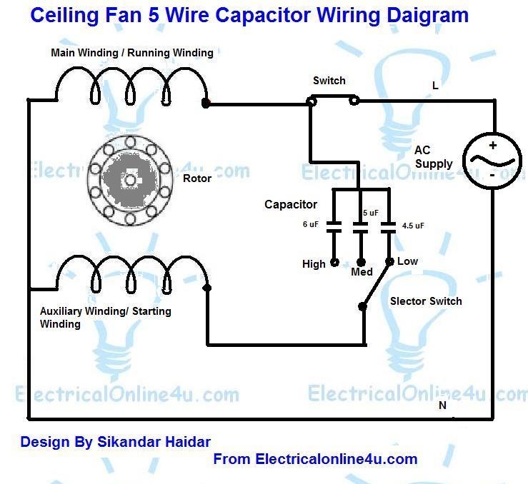
5 Wire Ceiling Fan Capacitor Wiring Diagram Cadician's Blog
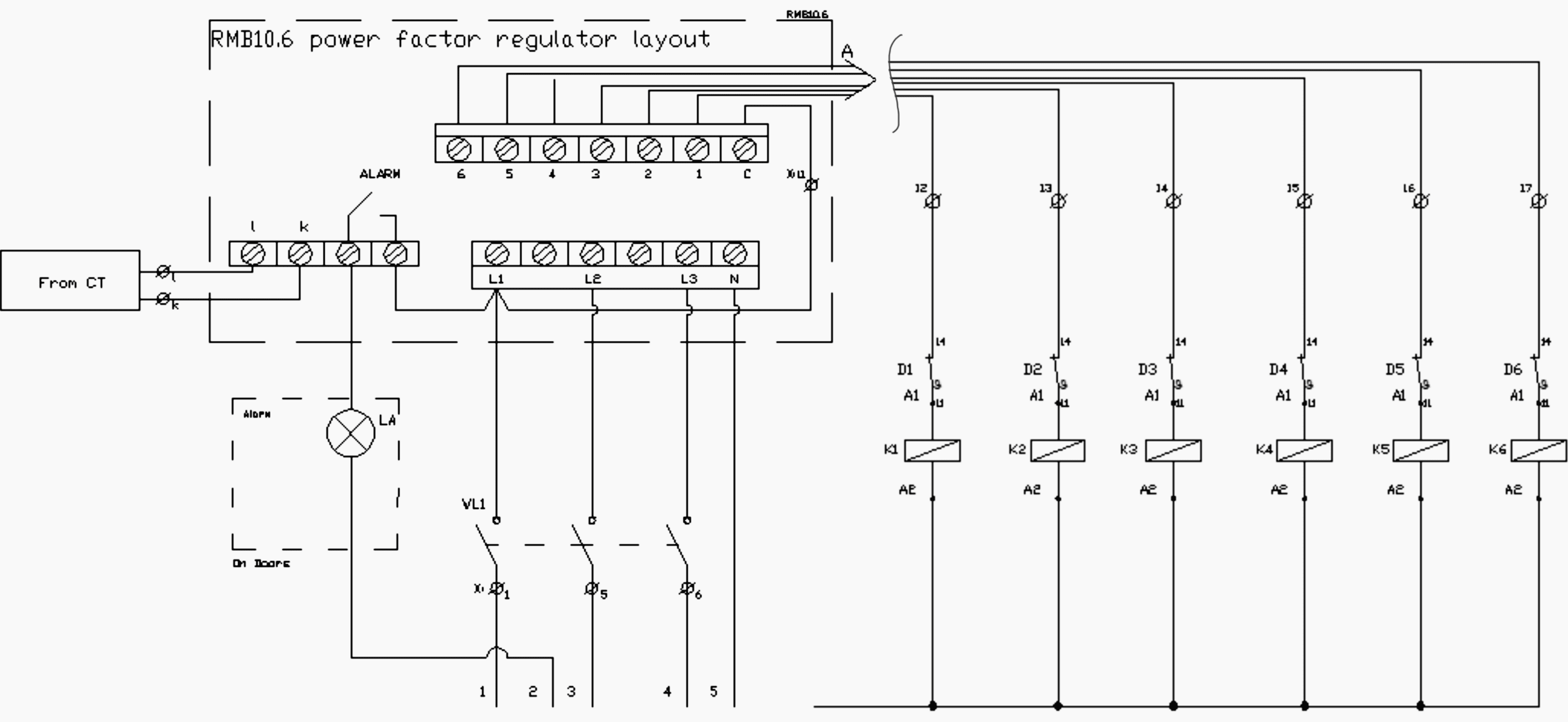
Stepbystep tutorial for building capacitor bank and reactive power compensation panel EEP
Stepbystep tutorial for building capacitor bank and reactive power compensation panel EEP
Basic circuit of a capacitor bank; L, C, R and R C represent the wiring... Download Scientific

Stepbystep tutorial for building capacitor bank and reactive power compensation panel EEP
5 Wire Ceiling Fan Capacitor Wiring Diagram Wiring Diagram
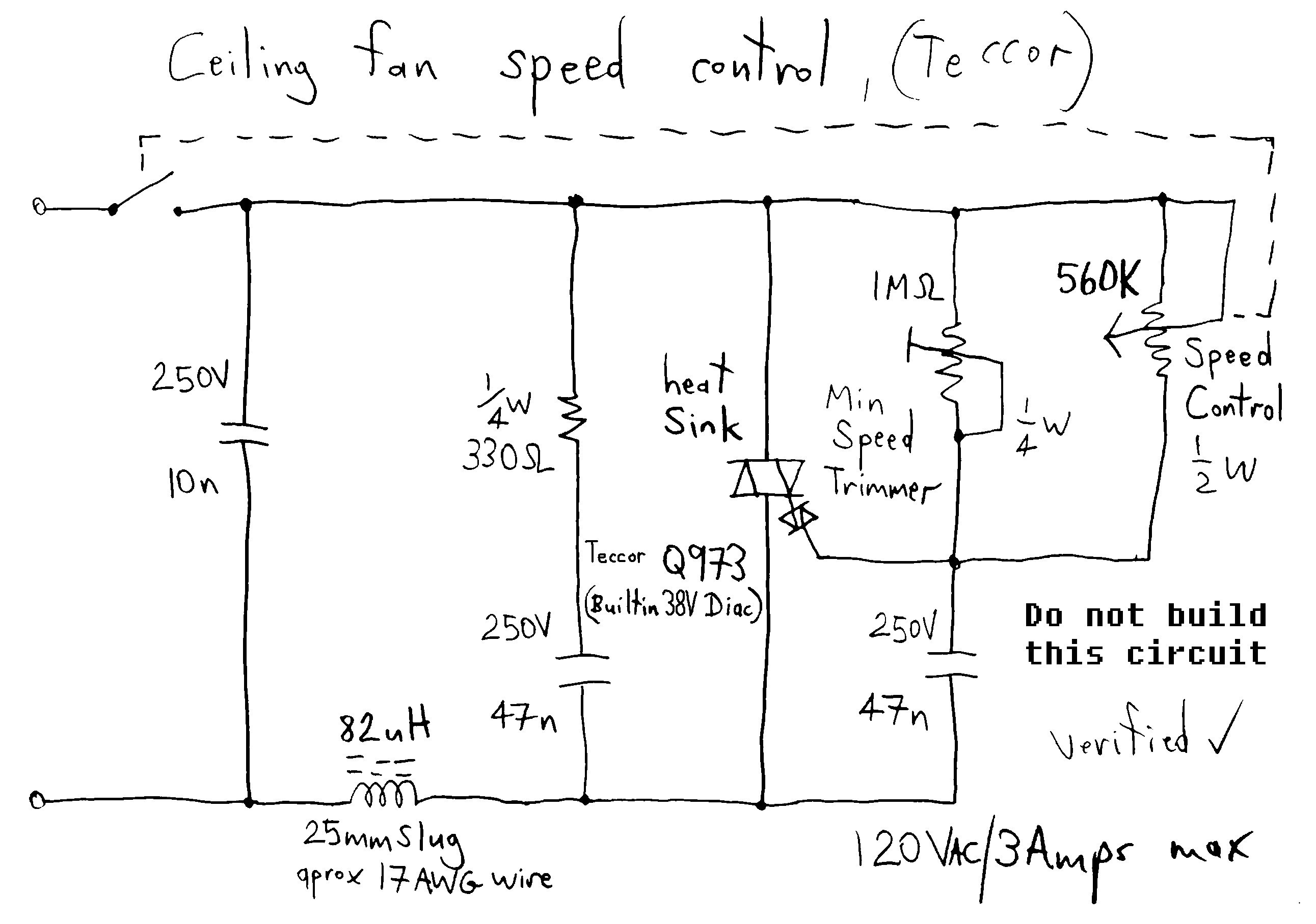
Images Of Ceiling Fan Capacitor Wiring Diagram Hunter Simple Capacitor Wiring Diagram
Stepbystep tutorial for building capacitor bank and reactive power compensation panel EEP
Wiring Diagram Of Capacitor For Car 1 Farad Capacitor How Many Amps Car wiring diagrams are
Stepbystep tutorial for building capacitor bank and reactive power compensation panel EEP
Hunter Ceiling Fan Capacitor Wiring Diagram Download

Dayton Capacitor Start Motor Wiring Diagram Free Wiring Diagram

8 Images Installing 5 Wire Ceiling Fan Capacitor And Description Alqu Blog
Ceiling Fan Capacitor Wiring Diagram Wiring Diagram Ceiling fan switch, Ceiling fan wiring

12+ Baldor Electric Motor Capacitor Wiring Diagram Wiring Diagram in 2020 Ac
5 Wire Ceiling Fan Capacitor Wiring Diagram Cadician's Blog
Electrical Control Panel Wiring Guide Popular 220V Wiring Diagram, Bcs 4 Element Gen2 Control
